English
 Views: 4 Author: SLVCN Engineering Team Publish Time: 2026-08-17 Origin: Site


During normal production, a pneumatic valve may open and close hundreds or even thousands of times without attracting much attention. The more important question is what happens when the air supply or control system fails.
An air compressor may shut down, pneumatic tubing may break or leak, or a solenoid valve may lose electrical power. When this happens, should the valve close, open or remain in its last position?
A properly specified pneumatic valve package should have a defined response to the relevant failure condition.
Two common terms used to describe pneumatic valve action are:
Air-to-Open (ATO)
Air-to-Close (ATC)
These terms are closely related to Fail-Close (FC) and Fail-Open (FO), but they do not mean exactly the same thing. Understanding the difference makes pneumatic valve selection much easier.
For a typical spring-return pneumatic actuator:
| Configuration | When Air Is Applied | When Air Is Lost | Typical Fail Position |
|---|---|---|---|
| Air-to-Open (ATO) | Valve opens | Spring closes the valve | Fail-Close (FC) |
| Air-to-Close (ATC) | Valve closes | Spring opens the valve | Fail-Open (FO) |
The easiest way to remember it is:
Air-to-Open: air opens the valve; loss of air closes it.
Air-to-Close: air closes the valve; loss of air opens it.
This relationship applies to a conventional spring-return arrangement. The actual fail action should still be confirmed according to the actuator configuration, valve mounting arrangement and control system.
An Air-to-Open (ATO) pneumatic valve uses compressed air to move the valve toward the open position.
In a typical spring-return arrangement:
Air applied → Valve opens Air lost → Spring closes the valve
Compressed air works against the internal spring force to open the valve. When air is lost, the spring returns the actuator and moves the valve to the closed position.
For this reason, Air-to-Open is commonly associated with Fail-Close.

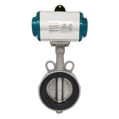
Example: Fail-Close Action of a Pneumatic Butterfly Valve
Fail-Close may be selected when continued flow after a failure creates a greater risk than stopping the flow.
Typical applications may include:
Fuel or combustible-gas isolation
Chemical dosing
Toxic or hazardous media
Steam isolation
Emergency shutdown lines
Consider a fuel supply line. If instrument air or control power is lost, allowing fuel to continue flowing may increase the severity of an incident. A spring-return actuator may therefore be configured to close the isolation valve automatically.
However, this does not mean every valve handling a hazardous medium should automatically be Fail-Close. The correct fail position depends on the function of the valve and which position creates the safer condition for the complete process.
An Air-to-Close (ATC) pneumatic valve works in the opposite direction.
In a typical spring-return arrangement: Air applied → Valve closes Air lost → Spring opens the valve
Compressed air moves the valve toward the closed position. When the air supply is removed, the spring returns the valve to the open position.
For this reason, Air-to-Close is commonly associated with Fail-Open.

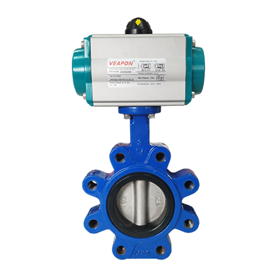
Example: Fail-Open Action of a Pneumatic Butterfly Valve
Opening a valve when air is lost may initially sound unsafe. In some processes, however, maintaining flow is safer than stopping it.
Cooling water is a common example. A reactor, compressor or other process equipment may require continuous cooling. If the cooling-water valve closes because instrument air is lost, the resulting temperature rise could damage the equipment or create a more serious process risk.
Fail-Open action may therefore be considered for:
Cooling-water systems
Equipment cooling circuits
Selected circulation lines
Certain ventilation applications
Some bypass or vent duties
These are examples rather than universal rules. The required fail position should always be determined according to the actual process and safety requirements.
Air-to-Open and Air-to-Close describe what pneumatic pressure makes the valve do.
Fail-Open and Fail-Close describe the required valve position after a defined failure.
A defined failure may involve loss of instrument air, electrical power or control signal, as well as a solenoid valve fault.
In a complete pneumatic valve package, the final fail action therefore depends not only on the valve and actuator, but also on the solenoid valve and control arrangement.
For a conventional spring-return system:
ATO → typically FC
ATC → typically FO
The required fail action should always be confirmed when the complete valve package is selected.
A spring-return actuator, also called a single-acting pneumatic actuator, uses compressed air in one direction and spring force in the other.
Because the spring stores mechanical energy, it can move the valve to a predetermined position when air is lost. Depending on the configuration, a spring-return actuator can be designed for either:
Fail-Close
Fail-Open
A double-acting pneumatic actuator uses compressed air for both opening and closing. Because a standard double-acting actuator normally has no return spring, complete loss of air does not automatically drive the valve to a predetermined open or closed position.
If a project requires a defined emergency position, the actuator and pneumatic control system should be selected accordingly.
Want to see the difference visually? Watch our video: Single-Acting vs Double-Acting Pneumatic Actuators.

Another common misunderstanding is that a Fail-Close valve must provide zero leakage.
These are two different requirements.
Fail-Close describes the position to which the actuator moves the valve after a defined failure. It does not define how tightly the valve seals once it reaches the closed position.
Actual shutoff performance depends on the valve and seat design, seat material, differential pressure, operating temperature, seat condition and available actuator torque.
The required fail position and shutoff performance should therefore be considered separately when selecting a valve.
The selection can start with one simple question:
If the valve loses air or control, which position creates the safer condition for the process?
If continued flow creates the greater risk, Fail-Close may be appropriate.
If interrupted flow creates the greater risk, Fail-Open may be appropriate.
For example:
Fuel isolation → often Fail-Close
Continued fuel flow may increase the hazard after a system failure.
Cooling-water supply → may be Fail-Open
Stopping cooling flow could result in equipment overheating.
Engineers should also consider the process medium, pressure, temperature, differential pressure, emergency shutdown philosophy, required operating speed and the consequences of both continued and interrupted flow.
There is no fail position that is universally safer.
The correct fail position is the one that creates the safer process condition during the defined failure.
Selecting a pneumatic valve does not have to be complicated.
If you are unsure whether your application requires Air-to-Open, Air-to-Close, Fail-Open or Fail-Close operation, provide us with your basic operating conditions:
Process medium
Valve type and size
Working pressure
Operating temperature
Available air pressure
Required fail position, if known
If some information is not available, that is also fine.
SLVCN engineers can review your operating conditions and help recommend a suitable valve, actuator and accessory configuration.
We supply pneumatic ball valves, pneumatic butterfly valves and pneumatic actuator packages for a wide range of industrial applications.
Air-to-Open and Air-to-Close describe the direction in which pneumatic pressure moves a valve.
For a conventional spring-return pneumatic actuator:
Air-to-Open → typically Fail-Close
Air-to-Close → typically Fail-Open
The correct fail position depends on which valve position creates the safer condition if air or control is lost.
If you are unsure which configuration is suitable for your application, send us your medium, valve size, pressure, temperature and available air pressure. Our engineers can help you select a suitable pneumatic valve and actuator configuration.