English
 Views: 0 Author: Site Editor Publish Time: 2026-08-10 Origin: Site


Electric actuators and pneumatic actuators are both widely used to automate ball valves and butterfly valves. Choosing between them is not simply a matter of deciding which actuator is "better."
The right choice depends on five main factors: the available power source, required fail-safe position, operating speed and frequency, control method, and total installed cost. Valve torque and the actual process conditions must also be checked before the actuator size and configuration are confirmed.
| Factor | Electric Actuator | Pneumatic Actuator |
|---|---|---|
| Power source | Electricity | Compressed air |
| Operating speed | Usually slower | Usually faster |
| Fail-safe operation | Requires a dedicated fail-safe design | Easily achieved with a spring-return design |
| On/off control | Direct electrical control | Commonly controlled by a solenoid valve |
| Modulating control | Often integrated into the actuator | Usually requires a positioner |
| Frequent cycling | Depends on the actuator duty rating | Well suited to frequent operation |
| Installation | No air piping required | Requires air supply and tubing |
| Typical application | Remote sites or locations without compressed air | Fast cycling and fail-safe applications |
This table provides a general comparison. Final actuator selection must be based on the valve torque, process conditions and required control function.
The available power source is usually the first factor to check.
If a plant already has a stable compressed-air or instrument-air system, a pneumatic actuator can be a convenient choice, especially when multiple automated valves share the same air supply.
When compressed air is unavailable, an electric actuator is usually easier to install because it only requires a suitable power supply and control wiring.
This makes electric actuation attractive for remote stations, water treatment systems, utility pipelines, irrigation systems and other installations without plant air.
The condition of the available utilities also matters. An unstable air supply can affect pneumatic actuator performance, while an unreliable electrical supply may require backup power or a dedicated fail-safe electric actuator.
Before selecting an actuator, determine what the valve must do if electrical power or compressed air is lost.
Depending on the process, the valve may need to:
Fail closed
Fail open
Remain in its last position
A spring-return pneumatic actuator is a common solution when a defined fail-open or fail-closed position is required. Compressed air moves the actuator in one direction, while internal springs return the valve to its predetermined safe position when the air supply is removed.
Electric actuators can also provide fail-safe operation. However, a standard electric actuator may require a mechanical spring, battery, supercapacitor, UPS or another stored-energy system to move the valve after a power failure.
The required fail position must be determined by the process safety assessment, not by actuator preference alone.
For example, a fuel supply valve may need to close automatically during a failure, while a cooling-water valve may need to remain open. The correct position depends on the consequences of losing flow or allowing flow to continue.
Pneumatic actuators normally open and close faster than conventional electric quarter-turn actuators. They are frequently used for process switching, emergency isolation and applications with a high number of operating cycles.
Electric actuators are suitable when the valve operates less frequently or when stroke time is not critical.
Faster movement is not always an advantage. Closing a valve too quickly in a liquid pipeline can create a pressure surge or water hammer. If this risk exists, the closing time should be evaluated as part of the valve and actuator selection.
Operating frequency is especially important for electric actuators. The actuator must have a duty rating that matches the required number of starts per hour and the expected running time.
A valve that operates twice per day has very different actuator requirements from one that cycles every few minutes.
Both actuator types can be used for on/off and modulating applications.
For basic open-and-close operation, electric actuators can receive direct electrical commands. Pneumatic actuators are commonly operated through a solenoid valve.
Limit switches or position feedback devices can be added to either system when the control room needs confirmation that the valve is fully open or fully closed.
For modulating control, an electric actuator may include an integrated control module that accepts signals such as:
4–20 mA
0–10 V
Other digital or fieldbus signals, depending on the actuator model
A modulating pneumatic actuator normally uses a pneumatic or electro-pneumatic positioner to move the valve to intermediate positions.
Before selecting the actuator and accessories, confirm:
Required positioning accuracy
Response speed
Control signal
Feedback signal
Loss-of-signal action
Required open and closed indication
The valve type also matters. A valve intended for throttling service must have a suitable flow characteristic and should not be selected based on actuator control alone.
The actuator purchase price is only one part of the total cost.
An electric actuator does not require an air compressor, pneumatic tubing or air distribution system. If compressed air is not already available, electric actuation can simplify installation and reduce additional equipment requirements.
A complete pneumatic valve assembly may include: Solenoid valve, Air filter regulator, Limit switch box, Pneumatic or electro-pneumatic positioner.
Where a reliable instrument-air system already exists, these components can be integrated efficiently across multiple automated valves.
Maintenance requirements are different as well. Electric actuators require attention to motors, gearboxes, wiring, electrical components and enclosure protection. Pneumatic systems depend on clean and stable air, properly maintained seals, and reliable solenoid valves and accessories.
The correct comparison is therefore the total installed and lifecycle cost, not simply the price of the actuator.
Whether the actuator is electric or pneumatic, it must be sized according to the actual valve operating torque—not valve size alone.
Torque can change because of:
Valve design
Valve size
Pressure differential
Seat material
Operating temperature
Process medium
Operating frequency
Service conditions
An undersized actuator may fail to fully open or close the valve. Excessive actuator torque increases cost and may place unnecessary load on the valve stem, mounting bracket and coupling.
Actuator selection should use the valve manufacturer’s torque data together with an appropriate service factor for the actual application.
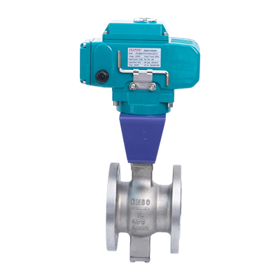
Electric and pneumatic ball valves may use a similar valve body, ball, stem and seat construction. The main difference is the actuator and its control system.
| Application requirement | Consider first |
|---|---|
| No compressed air available | Electric ball valve |
| Fast opening and closing | Pneumatic ball valve |
| Frequent cycling | Pneumatic ball valve |
| Simple fail-open or fail-closed action | Spring-return pneumatic ball valve |
| Remote installation with electrical power | Electric ball valve |
| Existing plant instrument-air system | Pneumatic ball valve |
| Modulating control | Either type, depending on the control requirements |
For example, an outdoor water pipeline that operates only a few times per day and has no instrument air may be well suited to an electric ball valve.
A process isolation valve that cycles frequently and must close automatically after loss of air or electrical control may be better suited to a spring-return pneumatic ball valve.
These are starting points only. Valve torque and process safety requirements must still be verified.
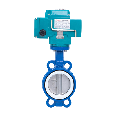
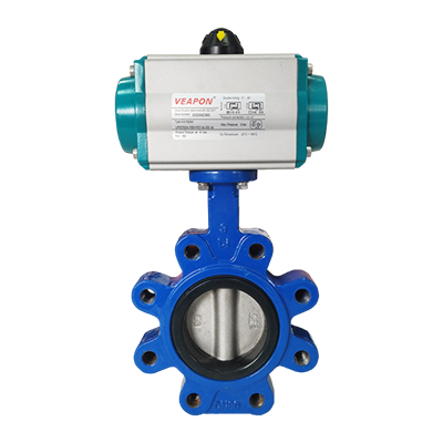
The same principles apply to butterfly valves. Electric butterfly valves are commonly selected where electrical control is readily available, while pneumatic butterfly valves are useful for fast or frequent operation. In both cases, actuator sizing must be based on the actual butterfly valve torque.
Valve size alone is not enough to select an actuator.
Before confirming a valve and actuator configuration, the SLVCN engineering team reviews:
Valve type and size
Process medium
Working pressure and temperature
Maximum differential pressure
Valve operating torque
Available voltage or air pressure
Required operating speed
Operating frequency
Fail-open, fail-closed or fail-in-place requirement
On/off or modulating control
Required control and feedback signals
Installation environment
For pneumatic systems, SLVCN can also select accessories such as solenoid valves, limit switch boxes, positioners and air filter regulators according to the required control function.
Electric and pneumatic valve actuators can both provide reliable automation for industrial ball valves and butterfly valves.
Electric actuators are a practical option for remote installations and locations without compressed air. Pneumatic actuators are well suited to fast operation, frequent cycling and applications that require a straightforward spring-return fail-safe function.
The final choice should consider the available power source, required fail position, operating frequency, control method, valve torque and total lifecycle cost.
If you are unsure which actuator is suitable, send SLVCN the valve size, pressure, temperature, process medium, available power source and required fail position. Our engineering team will review the application and recommend a suitable valve, actuator and accessory configuration.